
Calculating Gym Equipment Footprint: A Professional Procurement and Layout Guide
The High Cost of Underestimating Equipment Footprint
In my years overseeing facility setups, I have seen far too many procurement managers commit a fatal error: they buy equipment based on the static dimensions of the machine alone, completely ignoring the operational footprint. A single miscalculation in calculating gym equipment footprint can lead to a facility that feels claustrophobic, violates safety codes, or—worst of all—creates a high-risk environment where users collide or lose balance. The problem isn't just about the iron and steel; it is about the volume of space required for human movement and machine mechanics.
The primary cause of these failures is relying solely on manufacturer spec sheets without adding a buffer for dynamic motion. When you order a heavy-duty rowing machine or a functional trainer, you are not just buying the object; you are buying the kinetic area it occupies during a full range of motion. If you fail to account for this, your layout will fail during peak hours. To avoid this, we must transition from looking at simple length and width to understanding the total operational volume. Once you understand the difference between static and dynamic space, you can begin to structure your procurement lists with actual spatial realities in mind.
Identifying Static vs. Dynamic Dimensions
Before moving to floor planning, you must distinguish between these two critical metrics. Failure to do so is the most common mistake in facility design.
- Static Dimension: The actual physical measurement of the machine on the floor (the footprint).
- Dynamic Dimension: The maximum area reached by a user or a moving part during exercise (the operational footprint).
Recognizing this distinction is the prerequisite for any successful layout. With a clear understanding of these dimensions, we can move into the specific categories of equipment that demand different calculation methodologies.
Mastering Dynamic Range in Strength Equipment
Strength training machines often present the most complex challenges because their footprint is not fixed. A cable machine might have a small base, but the pulleys and weight stacks create an invisible boundary that changes as the user moves. If you only calculate the base, you will find your machines colliding during high-intensity training sessions.
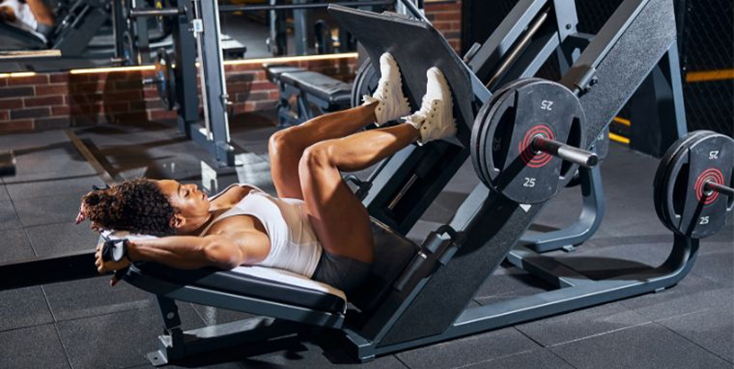
The mechanism of error here is the 'sweep area.' For example, a leg press or a smith machine has a predictable, albeit large, footprint. However, a cable crossover or a functional trainer has a highly variable footprint dictated by the length of the cables and the user's reach. When calculating the footprint for these pieces, you must look at the maximum outward extension of the cables. Industry benchmarks suggest that adding a safety buffer of at least 36 inches (roughly 90cm) around the machine's widest mechanical point is a minimum standard for commercial safety.
| Equipment Type | Static Footprint Focus | Dynamic Buffer Requirement | Common Failure Mode |
|---|---|---|---|
| Cable Cross/Functional Trainer | Base width and depth | Full cable reach + user stance | Cables catching on nearby racks |
| Smith Machine | Frame base dimensions | Barbell travel path (vertical/angle) | Users hitting side rails |
| Leg Press | Base plate size | Seat adjustment range + foot travel | Unsafe clearance for high-load sessions |
| Adjustable Bench | Bench length/width | Weight plate diameter + user reach | Collisions during set-up/takedown |
When reviewing equipment specs, always ask the supplier for the 'Maximum Operational Volume.' This data is often omitted in basic catalogs but is essential for professional-grade layouts. Once you have mastered the dynamic range of strength pieces, the next logical step is addressing the unpredictable nature of cardio equipment.
Calculating Footprint for High-Velocity Cardio Machines
While strength machines are largely governed by mechanical limits, cardio machines are often governed by human momentum and mechanical vibration. Calculating the footprint for a treadmill or a rowing machine requires a different set of parameters, particularly regarding the 'safety zone' behind and in front of the machine.
The problem arises when operators forget the 'safety exit' space. A high-speed treadmill has a static footprint, but if a user slips or needs to step off quickly, they require a significant clearance zone. Furthermore, rowing machines, which appear compact, have a massive longitudinal footprint when the user is at full extension and the seat is moving. If you place a rower too close to a wall, the user may hit the wall at the end of a stroke, leading to injury or equipment damage.
To verify your calculations, use the following checklist during the procurement phase:
- Treadmill: Add 6 feet (approx. 1.8m) of clear space at both the front and rear of the machine.
- Rowing Machine: Measure from the front of the machine to the absolute furthest point the seat can reach when the user is pulling.
- Elliptical: Account for the horizontal stride length of the longest-legged user.
- Stationary Bike: Include the swing space for the handlebars and the user's pedals.
By accounting for these buffers, you move from a cramped layout to a professional facility. This careful measurement of cardio space leads directly into the most overlooked aspect of floor management: the transit paths between machines.
Explore the complete technical specifications:
Optimizing Circulation and Transit Corridors
A common mistake is treating the area between machines as 'free space.' In reality, the space between two pieces of equipment is a vital component of the total gym footprint. If you treat the floor plan as a puzzle of machines fitting together, you will create a facility that feels like a warehouse rather than a professional training center.
The cause of poor circulation is usually an obsession with maximizing the number of machines per square foot. While this might look good on a spreadsheet, it destroys the user experience. A functional facility must have defined transit corridors that are wide enough for two people to pass or for a person to walk without bumping into a moving machine. For commercial environments, a minimum of 3 to 4 feet (approx. 1 meter) for primary pathways is the industry standard. If a machine's dynamic footprint overlaps with a transit path, you must increase the distance between the machines to ensure the path remains clear during use.
The Transit Space Hierarchy
Not all paths are equal. You should categorize your space into three distinct tiers:
- Tier 1 (Primary Paths): Main walkways between different training zones (e.g., from the entrance to the weight area). These should be widest.
- Tier 2 (Secondary Paths):** Spaces between individual machines within the same zone.
- Tier 3 (Personal Workspace): The immediate area surrounding the machine where the user operates.
Ensuring these tiers are respected will prevent the logistical bottlenecks that lead to client frustration. With your transit paths defined, you must now focus on how these zones interact with the flooring and structural elements of the building.
Explore the complete technical specifications:
Structural Constraints and Flooring Load Considerations
Once you have a theoretical layout, you must test it against the reality of your physical environment. Calculating the footprint is not just a horizontal exercise; it is a vertical one. The weight of the equipment, combined with the dynamic force of a user, creates a specific load profile that the floor must handle.
The failure mode here is structural fatigue or floor damage. For example, a heavy deadlift platform has a specific footprint, but the impact forces generated during a heavy lift extend far beyond the metal plates. If you place a heavy power rack on a floor with poor weight-bearing capacity or inadequate sub-flooring, the vibrations can affect the structural integrity of the entire building or cause nearby machines to shift. This is especially critical in multi-story buildings where high-impact training is occurring.
| Floor Element | What to Verify | Failure Mode if Ignored |
|---|---|---|
| Sub-floor Load Capacity | Max weight per sq. foot/meter | Structural cracking or floor sagging |
| Impact Absorption | Thickness of rubber mats/platforms | Noise complaints and equipment vibration |
| Support Columns | Placement and distance from machines | Obstruction of dynamic movement zones |
| Electrical/Data Outlets | Distance from machine placement | Tripping hazards from exposed cables |
Before finalizing your order, verify that your flooring provides enough damping to absorb the dynamic forces of the machines you've selected. This brings us to the final, and perhaps most critical, phase of the layout process: the inspection of the final installation.
Explore the complete technical specifications:
Verification and Final Layout Inspection Checklist
The last step in calculating gym equipment footprint is not the math—it is the physical verification. Even with perfect calculations, real-world variables like thick rubber matting or slightly uneven floors can alter your results. You must conduct a physical 'stress test' of your floor plan before the facility opens to the public.
The most effective way to do this is through a manual walk-through using 'placeholder' markers. Before the equipment arrives, use masking tape or chalk to mark out the exact static and dynamic boundaries of every machine on the floor. This allows you to see the layout as it will truly exist once the weight is added.
The Post-Installation Verification Protocol
Do not sign off on a layout until you have completed these three steps:
- The Full-Range Test: For every cable or adjustable machine, move the parts through their entire range of motion. Check if any part of the machine or the user's limb comes close to a wall, another machine, or a transit path.
- The Two-Person Pass: Walk through your designated 'Tier 2' and 'Tier 3' paths. Can a person walk through while someone is actively using the machine without feeling unsafe?
- The Obstruction Audit: Check all electrical cords and weight stacks. Are they within the designated footprint, or are they spilling into the walkways?
If any part of the protocol fails, you must go back to the procurement or layout stage. It is much easier to adjust a digital floor plan now than it is to move a 500lb leg press machine once it has been delivered and installed.
Explore the complete technical specifications:
Developing a Long-Term Footprint Maintenance Strategy
A professional facility layout is not a 'set it and forget it' task. As equipment ages, parts may wear, or you may decide to swap out a machine for a newer model. An effective operator must have a strategy for managing their space over time to ensure safety and efficiency remain constant.
The problem with long-term management is that equipment is often replaced by machines with different dimensions. A common mistake is assuming that a new machine in the 'same category' will have the same footprint. This is rarely the case. A modern cable machine might be more compact, but a heavy-duty version of a rower might be much longer. You must treat every equipment upgrade as a new footprint calculation task.
To maintain a professional standard, I recommend keeping a 'Space Registry' for your facility. This should be a digital document or a highly detailed CAD file that tracks every piece of equipment's static and dynamic dimensions. When you receive a new quote or a spec sheet for a potential purchase, immediately input that data into your registry to see how it affects your existing transit paths and safety buffers. This proactive approach ensures your facility remains a safe, high-performance environment for years to come.