
What a Gym Floor Plan Equipment Layout Should Include
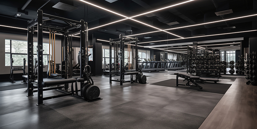
Commercial facility operators often face a critical bottleneck during the pre-launch phase: a poorly conceived spatial distribution that leads to traffic congestion, user injury, or inefficient equipment utilization. A flawed layout is not merely an aesthetic oversight; it is a structural deficit that can diminish the long-term ROI of high-cost assets. When equipment is placed without regard for clearance, user movement, or structural load, the facility faces premature wear and potential liability. To avoid these systemic failures, an optimized floor plan must integrate technical safety tolerances, logical zone categorization, and rigorous spatial buffers.
Defining the Critical Parameters of Spatial Buffer Zones
The primary cause of gym congestion is the failure to account for the 'active footprint' rather than just the static footprint of a machine. A static footprint is the physical dimensions of the equipment, whereas the active footprint includes the range of motion of the user and the necessary clearance for safety. Without these buffers, users frequently collide or enter the strike zone of moving parts, leading to high-risk incidents.
To mitigate this, operators must establish strict clearance minimums. For instance, a treadmill requires significantly more depth than its physical frame suggests to allow for the user's gait and the deceleration zone behind the machine. Failure to implement these zones results in a 'crowded' sensation that drives premium members away.
| Equipment Category | Static Footprint Requirement | Recommended Safety Buffer (Minimum) | Operational Failure Mode if Ignored |
|---|---|---|---|
| Cardio (Treadmill/Elliptical) | Length of Machine | 1.5m - 2.0m (Rear Clearance) | User falls off rear during deceleration |
| Free Weight Benches | Bench + Barbell Length | 1.2m (All Sides) | Collision during heavy lifting sets |
| Functional Strength (Cable Machines) | Machine Base Width | 1.0m (User Interaction Zone) | Cable entanglement or collision |
By establishing these non-negotiable distances, you build a foundation for safety. Once these buffers are understood, the focus must shift toward how different equipment types interact within specific functional zones.
Strategic Zoning for Workflow Optimization
A common mistake in facility design is the indiscriminate scattering of equipment, which disrupts the natural flow of a workout. If a functional training area is placed immediately next to a high-speed treadmill row without a physical or visual barrier, the kinetic energy of the functional movements can create a hazardous environment for the cardio users.
Efficient layouts utilize 'Logical Zoning' to separate high-intensity, high-impact activities from low-intensity, steady-state movements. This creates a mental and physical distinction that enhances the user experience. The following zones should be clearly delineated in any professional plan:
- Cardiovascular Zone: Often placed near ventilation or windows to optimize air circulation and user comfort.
- Resistance/Strength Zone: High-density area requiring durable flooring and proximity to weight storage.
- Functional/Mobility Zone: Open-floor area requiring minimum height clearances for overhead movements.
- Recovery/Stretching Zone: A low-traffic area shielded from heavy impact and high-volume noise.
Effective zoning prevents the 'cross-traffic' issue where a person moving between zones inadvertently disrupts someone mid-set. After defining these zones, the next step is ensuring the electrical and structural requirements of each zone are met.
Explore the complete technical specifications:
Electrical and Utility Integration Requirements
Even a perfectly zoned layout will fail if the technical infrastructure cannot support the load. A frequent pain point for operators is the discovery of insufficient power outlets or poorly positioned data ports once the equipment arrives. This leads to dangerous the use of extension cords, which are a major tripping hazard and fire risk.
When designing the layout, the plan must include a 'Utility Map' that aligns with the equipment placement. For example, high-end treadmills and smart machines often require dedicated circuits to prevent breakers from tripping during peak usage hours. Furthermore, the proximity of power outlets to the machine's power inlet must be strictly managed to keep cables out of the walking path.
Technical Verification Checklist for Utilities:
- Verify that all cardio equipment zones have dedicated electrical circuits to handle peak amperage.
- Ensure data ports for connected equipment are within a reachable radius to prevent cable tension.
- Map the placement of ventilation outlets to ensure air-flow does not interfere with heavy lifting zones.
- Check that lighting fixtures are positioned to avoid glare on digital consoles or screens.
Ensuring that the technical infrastructure is robust allows the facility to run without downtime. This structural readiness must then be paired with the specific flooring requirements dictated by the equipment usage.
Explore the complete technical specifications:
Material Selection and Flooring Durability Standards
The interaction between the equipment and the floor is a critical technical component of the layout. Using the wrong flooring in a high-impact zone is a primary cause of structural damage to the building and equipment instability. For instance, placing heavy power racks on standard rubber matting without a sub-floor dampening system can lead to micro-cracks in the concrete foundation over time.
The material selection must be based on the expected impact force and weight distribution of the machines. A professional layout specifies different floor types for different zones to optimize both safety and longevity.
| Target Area | Recommended Flooring Type | Key Performance Metric | Maintenance Requirement |
|---|---|---|---|
| Free Weight/Drop Zone | High-Density Vulcanized Rubber | Impact Absorption (Shock) | Monthly vacuuming and moisture check |
| Cardio/General Area | Low-Profile Commercial Tile | Slip Resistance (Coeff. of Friction) | Daily sanitization and sweep |
| High-Grade EVA Foam/Vinyl | Cushioning/Thermal Comfort | Regular deep cleaning of pores |
Matching the floor to the equipment's mechanical needs ensures the facility remains intact during heavy use. With the physical surface secured, the operator must now focus on the critical task of routine inspection.
Explore the complete technical specifications:
Preventative Maintenance Through Layout-Driven Inspection
A well-designed layout does not just facilitate movement; it facilitates maintenance. If machines are placed too closely together, technicians cannot access the back panels or motor housings for routine cleaning and repairs. This lack of access is a major cause of premature equipment failure, as dust and debris accumulate in hard-to-reach areas.
A professional floor plan includes 'Access Corridors'—specific pathways that remain clear even during peak hours, allowing for both user movement and technician utility. An operator should verify that these corridors are not just theoretical but are physically respected by the equipment placement.
The Maintenance Access Audit:
During the facility walkthrough, use a standardized checklist to verify that every piece of equipment has a minimum 60cm clearance for a technician to access service panels. If a machine is blocked by another piece of equipment, it is a failure of the original layout design. This lack of accessibility leads to increased labor costs and longer downtime when a machine eventually fails due to neglect.
Regularly reviewing these access points ensures that the equipment's lifecycle is maximized. However, even with perfect access, the operator must remain vigilant about the shifting trends in facility management.
Explore the complete technical specifications:
Navigating Trends in High-Tech Equipment Integration
As the fitness industry shifts toward more connected and AI-driven equipment, the requirements for a gym floor plan are evolving. Modern machines are no longer just mechanical weights; they are data-generating terminals that require more robust connectivity and power stability. This evolution presents a new challenge: the layout must be adaptable to a changing technological landscape.
Future-proofing a layout means designing for modularity. This involves creating 'Flex Zones'—areas where the equipment can be easily swapped or upgraded without necessitating a complete overhaul of the electrical or flooring infrastructure. For instance, a zone currently used for strength training might eventually transition to a high-tech recovery hub with specialized diagnostic tools.
To stay competitive, operators must view their layout as a living document rather than a static blueprint. This requires an ongoing assessment of how technology is changing the footprint and utility requirements of the equipment being procured. Building a space that can evolve is the ultimate safeguard for a facility's long-term profitability.
Final Verification of the Layout Efficiency
Before the first piece of equipment is bolted down, a final verification of the entire plan is mandatory. This is where the theoretical layout meets the practical reality of the space. Many operators skip this phase, only to realize too late that a significant piece of machinery is too close to a pillar or that a doorway is too narrow for a weight plate to pass through.
The final step is to perform a 'Virtual Walkthrough.' Using a scaled 2D or 3D model, simulate the movement of a user through each zone. This simulation should include the addition of the safety buffers discussed earlier. If the virtual user encounters constant bottlenecks or high-risk zones, the layout must be redesigned. Only after this rigorous testing of the floor plan can an operator proceed to procurement with confidence.